Overview
In this part of our AE Grid Series, we'll cover the setup of a sliding grid, where footage clips can be organized in rows and columns, and can be animated: collapsed or resized.
We should be able to easily change the grid size (number of rows and cols), and rapidly swap footage items, or rearrange the order within the grid.
The objective of this guide is to explain the rig in detail, to gain the ability to fully customize the controls, and lay out the groundwork for creating grids of any size.
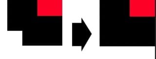
Below is a quick example with two horizontally stacked grids of 25 squares. Each square is a PRECOMP, so the contents can be easily edited while maintaining the proportions:
Download the AE Project File
To follow along, download the After Effects project file .aep from our Github page.
 gfxhacks
Note: If you get any expression errors when you open the project, make sure the Expression Engine is set to Javascript in Project Settings > Expressions or CMD/CTRL SHIFT ALT/OPT K. This allows us to use some of the newer Javascript methods available. More info here: Syntax differences between the JavaScript and Legacy ExtendScript expression engines.
Quick Start Guide
Rig Overview
At it's core, the rig is structured with the following elements:
CONTROL Layer:
- This is the brain of the rig, and is where the grid size can be set: the number of rows and columns and their dimensions. The grid layout algorithm will be run here.
GRID STROKE Layer:
- This is a shape layer with a stroke applied (no fill). It draws a border around every grid item.
GRID ITEM (three layers):
- Comprises of a Footage precomp, a Shape layer that acts as a mask for the precomp, and a Text layer that identifies the grid item position in the comp view. All 3 layers of a grid item must be duplicated when creating a new grid item. The footage precomp also has to be duplicated in the project panel, and made sure that the layer source matches that duplicate.
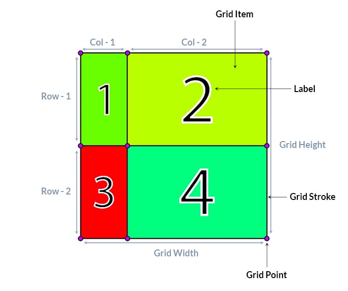
The Grid Layout is setup using Shape layers, in the form of rectangles - that will act as masks for the precomps. Those Shape layer masks are constructed using the createPath() method, by specifying the 4 path points coordinates (4 corners) that define the rectangle shape. We'll refer to those as the Grid Cells.
Since the dimensions of a cell are arbitrary, we'll be using ratios instead of pixel values for the row/col sizes. When adjusting the size of the grid, the cells will readjust in size automatically while maintaining the same ratio.
For the ratios to make sense, a 0-100 range is recommended; to be considered as percentages of the dimension of the grid. A grid of 2x2 with Col - 1 set to 25, and Col - 2 set to 75 would display as Row - 1 taking up 25% of the total grid height, and Row - 2 the remaining 75%.
Basic Walkthrough
Let's go through a basic example to get a practical understanding of the grid:
The default setup comes with a 2x2 grid (2 rows and 2 columns). Let's say we want a 2x3 grid layout (2 rows and 3 columns) instead - we'll need to add a third column...
We first create, by duplication, a new Row and Col slider controls in the Grid Controls layer effects panel; for the third row and col:
Row - 3Col - 3
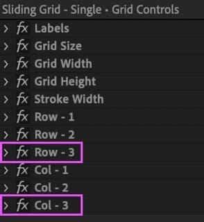
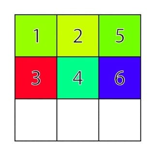
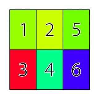
Then set the Grid Size (from the same effects panel) to 3. This should draw a 3x3 grid. Note: the empty cells - we'll need to create those missing grid items for that last column, but can disregard the last row since we'll collapse it anyways.
3x3 grid layout with new empty cells.Let's head over to the timeline panel and make sure the Shy switch is turned off, revealing all layers.

Let's select and duplicate the last grid item (item 4) - this comprises of the 3 layers: Grid Item, Matte, and Label. We'll repeat this step once again so we now have a total of 6 grid items.
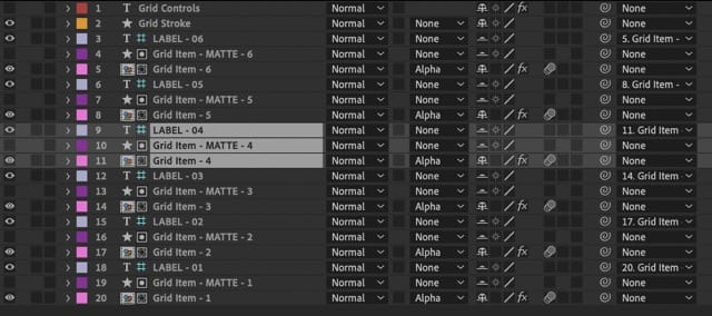
4 (all three layers), to create item 5 and 6.Now let's head over to the Project Panel and locate one of the grid items footage precomps, and duplicate that. With the new duplicate selected, we can head over to the timeline panel and choose the Grid Item - 5 footage precomp. By pressing CMD OPT / (macOS), CTRL ALT / (Win) we'll replace the current footage precomp with the new duplicate one. Repeat this procedure for item 6.
Notice how the new grid items (5 and 6) are stacked on top of item 4 since we duplicated them - let's select grid item 5 and head over to the effects panel. Here we can set the new grid position for this grid item: Column 3, Row 1.
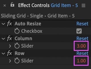
3 and Row 1 position for Grid Item - 5.Let's do the same for grid item 6 but positioned in: Column 3, Row 2. We can of course rearrange the existing grid items in whichever order we prefer.
Finally we can collapse that last row - by opening the effects panel of the Grid Controls layer and setting the previously created Row - 3 slider value to 0.
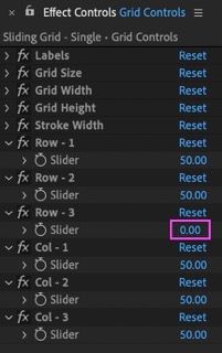
0.Note: All other values can be kept at 50 to obtain a uniform grid - where all column widths are equal, and all row heights are equal. This can be the confusion when working with ratios - always keep in mind that the widths and heights are relative to each other, measured against the total grid dimensions. Try setting all Column sliders to 100, or 1 - as long as the values are the same for all sliders, the calculated sizes will also be the same, and we'll obtain a uniform grid. In essence you can define your own scale to work with (although we recommend working with a percentage scale: 0-100 - relative to the width and height of the grid).
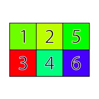
3x2 grid with third row collapsed.But what if we wanted to have a grid of squares? We can simply adjust the height of the grid accordingly. So if there are three rows, divide the current grid height of 1000 by 3, then multiply the result by 2. In After Effects we can input this equation directly in the value box and it will be solved instantly.
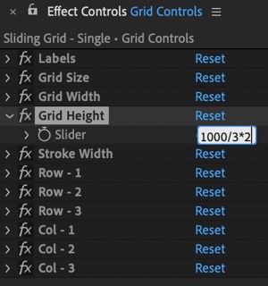
The rows adjust to the new height, resulting in square cells!
Grid Controls Reference
Below is a reference of all current grid controls, categorized by layer.
Grid Control Layer
| Control | Decription |
|---|---|
| Labels | Toggles Labels visibility. |
| Grid Size | Sets the number of rows and columns. |
| Grid Width | Grid Width in pixels. |
| Grid Height | Grid height in pixels. |
| Stroke Width | Border thickness around grid cells. |
| Row - {n} | Height of row {number}, as a ratio relative to the total grid height. |
| Col - {n} | Width of column {number}, as a ratio relative to the total grid width. |
Grid Item Controls
Controls for each footage layer.
| Control | Decription |
|---|---|
| Auto Resize | If On, the contents automatically scale to fill the cell. |
| Column | In which column the grid item will be located. |
| Row | In which row the grid item will be located. |
Double Grid Setup Controls
| Control | Decription |
|---|---|
| Partition | Sets the amount of comp space the left/top grid takes. The right/btm grid takes up the rest. |
| Stack | Whether the two grids are stacked horizontally or vertically. |
Understanding the Rig
The Grid Control Layer
The GRID CONTROL layer is our control center for the grid. It features the various effect controls to adjust the grid.
There is only one expression here, found in the source text layer property. Its purpose is to calculate the coordinates of each grid cell - we'll go over how and why this has been done in a source text layer later on. Let's dive into the expression's code:
// get grid specs
const grid_width = effect("Grid Width")("Slider").value;
const grid_height = effect("Grid Height")("Slider").value;
const grid_size = effect("Grid Size")("Slider").value;

// slider control values for rows and cols will be stored in these arrays:
const col_widths=[], row_heights=[];

// get all Slider Controls for col widths and row heights, and store in respective arrays
// limit value range with clamp() - e.g: 0-100 [optional]
for (let i=1; i<=grid_size; i++) {
    col_widths.push(effect("Col - "+i)("Slider").value);
    row_heights.push(effect("Row - "+i)("Slider").value);
};

// function to calculate sum of values in an array
const reducer = (accumulator, currentValue) => accumulator + currentValue;

// calculate the sum of the slider values for col widths and row heights
const col_widths_tot = col_widths.reduce(reducer,0);
const row_heights_tot = row_heights.reduce(reducer,0);

// construct a 2-dimensional array with the corner coordinates of each cell.
const grid_points = [];

// iterate through rows
for (let pcol=0; pcol<=grid_size; pcol++) {
	grid_points[pcol]=[];
	// iterate through cols
	for (let prow=0; prow<=grid_size; prow++) {

		// coordinates are the sums of all previous widths summed
		const w = col_widths.slice(0,pcol).reduce(reducer,0) / col_widths_tot;
		const h = row_heights.slice(0,prow).reduce(reducer,0) / row_heights_tot;

		const x = (w-0.5)*grid_width;
		const y = (h-0.5)*grid_height;

        grid_points[pcol][prow] = [x, y];
	}
}

// convert array to a string
JSON.stringify(grid_points);
First thing we'll see are the references to the grid specs:
// get grid specs
const grid_width = effect("Grid Width")("Slider").value;
const grid_height = effect("Grid Height")("Slider").value;
const grid_size = effect("Grid Size")("Slider").value;
The grid_width and grid_height allow us to set the overall dimensions of the grid, independent of the comp size.
The grid_size specifies the number of rows/columns in the grid. We've kept this value uniform (same number of rows and columns), since we can break this uniformity by collapsing individual rows or columns instead; simply by setting the appropriate Row/Col Slider control value to 0 - just like in our Basic Walkthrough example.
Gathering Cell Size Values
Next up we declared the empty Row/Col size arrays - ready to be filled with the Row/Col slider control values:
// slider control values for rows and cols will be stored in these arrays:
const col_widths=[], row_heights=[];
To reference each Row and Col slider that we've added in the effects panel (based on the grid_size), we can use a For Loop to iterate through the specified grid_size value, for both Rows and Cols, and the values are pushed (appended) to the col_widths or row_widths arrays respectively.
// get all Slider Controls for col widths and row heights, and store in respective arrays
for (let i=1; i<=grid_size; i++) {
    col_widths.push(effect("Col - "+i)("Slider").value);
    row_heights.push(effect("Row - "+i)("Slider").value);
};
Let's get practical and use the following values as an example for a 2x2 grid as we move forwards:
| Slider Control | Value |
|---|---|
| Grid Width | 1000(px) |
| Grid Height | 1000(px) |
| Grid Size | 2 |
| Row - 1 | 50 |
| Row - 2 | 50 |
| Col - 1 | 25 |
| Col - 2 | 75 |
With the above specs, the grid would look like this:
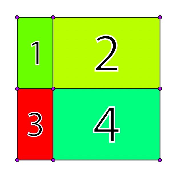
Based on the example above, once the For Loop runs, the values of each Row/Col size sliders will be retrieved and pushed to their respective array:
col_widths = [25, 75];
row_heights = [50, 50];
2x2 grid.Calculating the Grid Point Coordinates
Now comes the fun part! Let's break down the algorithm used to calculate the coordinates [x,y] for each grid point. These coordinates will be used in the CreatePath() method, to draw each cell of the grid, as well as the Grid Stroke. We'll look at that later on. For now keep in mind that the x in the coordinates will be defined by the Column sizes and the y by the Row sizes.
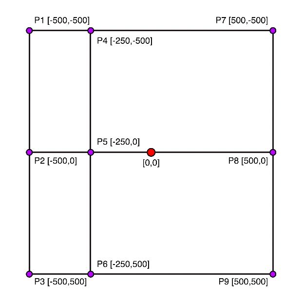
Notice the red [0,0] origin point at the center of the comp (figure above). This will be the center of the grid. Each point coordinate (purple) will all be relative to this origin point. This will allow the grid to remain centered when changing its dimensions.
The goal of the algorithm is not only to calculate the coordinates of each point of the grid, but to store them in a way that can be easily referenced by the other comp layers - in order to actually draw the grid.
Structuring Our Data
We'll use a 2-dimensional array to store those coords, based on the number of Rows and Columns as specified in the Grid Controls. Let's look at how this array type differs from a 1-dimensional array.
If we insert our grid point coordinates in a 1-dimensional array, it would look like this:
arr_1d = [P1, P2, P3, P4, P5, P6, P7, P8, P9]
and the first point coordinates P1 would be accessed using arr_1d[0] (Array item indexes always start from 0).
A 2-dimensional array would instead look like this (an array within an array):
arr_2d =
[
  [P1, P2, P3],
  [P4, P5, P6],
  [P7, P8, P9]
]
Notice how the data appears in rows and columns. A 2-dimensional array is a great fit for our case, as it naturally allows us to structure our data in a table style (rows/cols) - from which we can retrieve our grid point values more intuitively.
Note: This may be confusing at first, since the rows and columns in the array don't directly represent the cells of the grid - for a 2x2 grid there are 3x3 points. So we'll differentiate by specifying the former as Grid Cells, and the latter as Grid Points. Whenever we are dealing with the createPath() method, we'll be dealing directly with the Grid Points array.
So, in regards to Grid Points, to access that first point coords P1 from the 2d array above, we'll need to use arr_2d[0][0] - as in arr_2d[first_row][first_col]. Point P4 would be retrieved with arr_2d[1][0] - [second_row][first_col]. Point P9 would be arr_2d[2][2] - [third_row][third_col], and so on. In essence, to access any value we'll first need to specify the row number, followed by the column number: arr_2d[row][col].
Note: Learn more about Arrays on MDN Web Docs.
To generate the 2d array above we can implement a Nested For Loop: a For loop within a For loop. So for each outer For loop iteration, the inner For loop will complete all its iterations. In practice, it looks like this:
Note: Keep in mind that a grid of 2x2 Grid Cells has 3x3 Grid Points (as seen in the grid figure above), hence both for loops will run 3 times, and calculate the coords of 9 points.
grid_size = 2;
// declare empty array first, ready to be filled.
grid_points = []
// iterate through rows, based on grid_size (runs 3 times: 0,1,2)
for (row=0; row<=grid_size; row++) {
	grid_points[row]=[];
  // for each row, iterate through all cols in that row (also runs 3 times: 0,1,2)
  for (col=0; col<=grid_size; col++) {
    grid_points[row][col] = {coords_calculation}
  }
}
Note: Nathan Sebhastian has a nifty explanation of how nested loops work in Javascript on his website.
Coordinates Equation
Next we'll look at the coordinates equation to help us calculate each grid point coordinate - each solved coord will be stored into the 2d Grid Points array: grid_points[row][col] = {coords_calculation}.
x = (current_col_widths_total/col_widths_total - 0.5) * grid_width;
y = (current_row_heights_total/row_heights_total - 0.5) * grid_height;

P1 = [x, y]
For each x and y, the equation will be run by however many iterations are specified in the grid size - 2x2 in our example, so 3 times for each axis. The current_col_widths_total holds the sum of: the column size of the current iteration, and the sum of all previously iterated column sizes. Same thing for the row sizes.
col_widths = [25, 75];
row_heights = [50, 50];

// col_widths:
//  iteration 1 : 0
//  iteration 2 : 0 + 25
//  iteration 3 : 0 + 25 + 75

// row_heights:
//  iteration 1 : 0
//  iteration 2 : 0 + 50
//  iteration 3 : 0 + 50 + 50
The col_widths_total and row_heights_total represent the total of all row/col sizes, respectively:
col_widths_total = 0 + 25 + 75 = 100
row_heights_total = 0 + 50 + 50 = 100
So we'll be dividing the current accumulation of sizes by the sum of all sizes, during each iteration: current_col_widths_total/col_widths_total. This will always yield a result between 0-1, ensuring that the cumulative size is always relative to the total size.
The resulting values for rows and cols are both then multiplied by the grid size, returning the point coordinates that we are after.
Now, if you refer back to the figure above depicting the Grid Points, we want our [0,0] origin point to be at the center of the grid - this allows the grid to be resized relative to it's center.
In AE, the [0,0] origin point is by default in the top-left corner of the comp so the 0-1 output range is relative to that origin point. To adjust the range to be relative to the center origin point instead, we need to offset it by half: 0.5. Our new range will be [-0.5, 0.5].
This will become clearer once we look at how the equation is implemented in our inner for loop, and its results.
Reducer Function
To help us calculate both the cumulative row/col size in each iteration, and the total row/col size, let's setup a reducer function. This type of function can be used to efficiently sum values in an array together.
In practice any or all array values can be passed to the reducer function through the reduce() method, and summed up.
Let's see how this setup is used to calculate the total row and col widths:
Note: 0 is passed as a second argument to specify that the summing needs to start from zero.
const reducer = (accumulator, currentValue) => accumulator + currentValue;

const col_widths_tot = col_widths.reduce(reducer,0);
const row_heights_tot = row_heights.reduce(reducer,0);

// col_widths_total = 0 + 25 + 75 = 100
// row_heights_total = 0 + 50 + 50 = 100
Note: Read more about reducer functions on MDN Web Docs.
Implementing the Equation
Let's move on to implementing the coordinates equation in the inner for loop - to make it clearer we've broken it up into segments, but the outcome is the exact same.
const grid_points = [];

// iterate through rows
for (let row=0; row<=grid_size; row++) {
    grid_points[row]=[];
    // iterate through cols
    for (let col=0; col<=grid_size; col++) {

		const w = col_widths.slice(0,col).reduce(reducer,0) / col_widths_tot;
        const h = row_heights.slice(0,row).reduce(reducer,0) / row_heights_tot;

		const x = (w-0.5)*grid_width;
		const y = (h-0.5)*grid_height;

        grid_points[row][col] = [x, y];
    }
}
The first step is therefore to calculate the sum of the col/row size for the current iteration, and all previous col/row sizes. This can be easily done with our new reducer function - by passing it a portion of the col_widths/row_heights arrays based on the current iteration index.
To isolate the array values to pass to the reducer function, we'll be using the slice() method - as the name implies we can use it to slice the array within a given index range.
Let's take the first iteration as an example, and plug in the sample values we've been using.
// slice(0,0) returns an empty array: []
const w = [25,75].slice(0,col).reduce(reducer,0) / col_widths_tot;
const h = [50,50].slice(0,row).reduce(reducer,0) / row_heights_tot;
// result: [0,0]
Coordinates equation with sample values.
For the first iteration, the slice() method clips the array at index 0: slice(0, 0), resulting in an empty array: [] - meaning no actual values are passed to the reducer function. Since we specified that the summing starts from 0, in that second argument: reduce(reducer,0) - the output remains 0 since there are no values passed to add up. For the second iteration, the width array passed to the reducer would be [25] that would not need to sum anything. During the third and final iteration, the array passed would be [25, 75], and this time the reducer would sum the two values together for a total of 100.
The same slicing and summing procedure is run for the height (h) .
The sum result for both widths and heights is then divided by the row/col size totals, to find the width and height relative to the total size. For the first iteration where the result is 0, the outcome of the division is of course also 0 (zero divided by any number is zero). So we now have the width and height of [0,0] that translates to the coordinates of the first point.
Due to our grid origin point being at the comp's center, we'll need to offset by half, as well as multiply by the specified grid width and height, respectively.
In our sample values we specified a grid size of 1000px, so our first point coord will be: [x,y] = [-500,-500], as demonstarted below
const x = (w-0.5)*grid_width;
const y = (h-0.5)*grid_height;

grid_points[row][col] = [x, y];
// grid_points[0][0]: [-500,-500]
Calculating the coordinates for the remaining 9 points in a 2x2 grid will give us the following array:
grid_points =
[
  [[-500,-500], [-250,-500], [500,-500]],
  [[-500,0]   , [-250,0]   , [500,0]]   ,
  [[-500,500] , [-250,500] , [500,500]]
]
2x2 grid.We can now convert this generated grid array into a string, to allow the other layers to reference the computed coordinates values directly.
// convert array to a string
JSON.stringify(grid_points);
JSON.stringify().Referencing the Grid Array from Other Layers
To layout the grid, all grid item cells would have to reference one another in order to position themselves - or at least solve a positioning equation, based on a predefined number of rows and columns.
For large animated grids this can be very inefficient, especially if referencing other layers, since calculations are run on each frame and would be performed by each property expression for every layer.
To mitigate this, we would rather perform the calculations once for the entire grid in a single layer, and then have each cell reference the respective solved position from that layer.
We can therefore output an array of computed values; a matrix that holds the 2-dimensional position value of each cell in the grid. Then each cell, based on an identifier, can retrieve their own relevant position value.
But how can we achieve this in After Effects, where we can only reference other layers' properties?
We can output the Array as a String in a text layer's source text property, and reference that. Then, we convert that text string back into an array, so we can work with it using Javascript's powerful array methods. The conversion is handled by the JSON Object.
arr = [1, 2, 3, 4];

str = JSON.stringify(arr);
// "[1, 2, 3, 4]" - quote marks represent a string

arr = JSON.parse(str);
// [1, 2, 3, 4]
 Alligator.ioDeveloper and author at DigitalOcean.
The Grid Items
A Grid item consists of a Footage Precomp, a Shape layer that acts as a mask for the precomp, and a Text layer that identifies the grid item position in the comp view. Those are three separate layers that operate together to form an individual cell in the grid layout.
Let's look at these individually and understand how they operate together.
1. Shape Layer Mask
At the core of the Shape layer is a path that draws the boundaries of the cell using the createPath() method. The cell position can be set in the effects panel of the Footage Precomp layer below; by specifying a row and col number.
We first retrieve the computed Grid Points string from the CONTROL layer and parse it, converting it to an array.
grid_points = JSON.parse(thisComp.layer("Grid Controls").text.sourceText);Then we get the row and col numbers that we specified in the effects panel. So if we want this grid item to be the first cell of the grid we can specify Row: 1 / Column: 1 in the slider controls - in a 2x2 grid as in our example, the last cell would be specified as Row: 2 / Column: 2.
Note: We actually need to subtract by 1 since we are dealing with arrays; where the first item is at position 0.
// get the specified row and column coordinates and normalize
const row = thisComp.layer(index+1).effect("Row")("Slider").value - 1;
const col = thisComp.layer(index+1).effect("Column")("Slider").value - 1;
It's time to construct the cell and draw it. We use the row and col pair we picked to retrieve the actual point coordinates from the Grid Points array, for each corner of the cell. Then we can use the createPath() method to draw the cell. This method will go through each specified point sequentially and draw a connecting line through them.
The true flag as the last argument specifies to close the path.
// construct the cell boundaries in clockwise order
// starting from the top left corner
const cell_corners = [
	grid[col][row], // 1st point - top left
	grid[col+1][row], // 2nd point - top right
	grid[col+1][row+1], // 3rd point - btm right
	grid[col][row+1] // 4th point - btm left
]

// draw the cell
createPath(cell_corners, [], [], true);
Note: Learn more about the createPath() method.
Since we are working with the grid origin point set to the center of the comp, we need to ensure the shape layer origin point is also centered.
We can add a simple expression in the position property to constrain to center, while making sure the anchor point property value is set to [0,0].
const x = thisComp.width/2;
const y = thisComp.height/2;

[x, y]
2. Footage Precomp
Below the Shape layer mask is the Footage precomp - this is where the cell contents go. It is setup as a precomp so we can easily edit the contents independent of size or complexity (and avoid disproportions as the cell resizes).
This precomp layer has the alpha matte option enabled to make use of the Shape layer above as a mask, and hide anything outside of the cell boundaries.
The expressions here are featured only in the position and scale properties:
Position
For the position, we first reference the Grid Points array, then grab the col and row number as specified in the respective Slider controls, in the effects panel.
We want the precomp to always remain at the center of the cell, so we can use this equation, for x and y, referring to the computed Grid Points coordinates of the current cell:
x = (top_left_corner + top_right_corner) / 2
y = (top_left_corner + bottom_left_corner) / 2
in practice:
// extract coords from grid specs array
const x = (grid_points[col][row][0] + grid_points[col+1][row][0]) / 2;
const y = (grid_points[col][row][1] + grid_points[col][row+1][1]) / 2;Scale
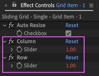
Ideally the scale of the grid item precomp adjusts relative to its cell size, while maintaining its proportions. But we've added the option to turn this behaviour off and manually set the scale of the precomp, for more flexibility. With the auto-resize feature on, the precomp will always fill the cell.
The auto-resize can be toggled from the checkbox control in the precomp's layer effects panel.
We first retrieve the grid dimensions as set in the CONTROL layer, as well as the checkbox value for the auto-resize feature:
// get grid specs
const grid_width = thisComp.layer("Grid Controls").effect("Grid Width")("Slider");
const grid_height = thisComp.layer("Grid Controls").effect("Grid Height")("Slider");
const is_auto_resize = effect("Auto Resize")("Checkbox").value;The dimensions of the Shape layer mask above can be retrieved with the sourceRectAtTime() method. This will give us the mask width and height in pixels.
// get Shape layer mask dimensions
const { width, height } = thisComp.layer(index - 1).sourceRectAtTime();
We then need to convert those dimensions to percentages. This will give us the dimension of the cell, relative to the grid size.
// find cell percentage size relative to grid size
const w = width / grid_width * 100;
const h = height / grid_height * 100;
To fill the cell, we need to detect whether the width is larger than the height or vice-versa.
To detect which dimension is larger, we can use a simple Conditional Statement or rather, a Shorthand Conditional Statement: a shorter way of writing a conditional statement, using Conditional Ternary Operators.
So if the cell size is set to have a larger width, the scale of the precomp will resize based on that width value, otherwise it will follow the height - this is dynamic so will switch as soon as one dimension value overtakes the other.
// set size based on larger dimension (fill the cell)
const size = w > h ? w : h;
Once again using a shorthand conditional, we can check whether the auto-resize option is turned on and apply the final scale value. If turned OFF, we simply return the current value of the scale property, allowing us to manually control it.
// constrain sizes if auto-resize is set to ON
is_auto_resize ? [size, size] : value
Below is a comparison of the auto-resize option toggled OFF (cell 1), and ON (cell 2).
auto_resize feature comparison.3. Cell Identifier
This layer acts as an identifier for the underlying cell, by displaying it's index. It is solely for reference and in fact, it is set as a guide layer (RMB click on layer > Guide Layer). It is parented to the footage precomp.
Since each precomp has a unique number at the end of the name (e.g. 1, 2..., 10...), we can retrieve that number as the identifier, and display it from the text layer's source text property; using the following expression:
thisComp.layer(index + 2).name.match(/\d+$/);
To extract those numbers at the end of the name we can use the Javascript match() method, combined with the power of a Regular expression.
A regular expression (shortened as regex or regexp; also referred to as rational expression) is a sequence of characters that define a search pattern. Usually such patterns are used by string searching algorithms for "find" or "find and replace" operations on strings, or for input validation. — Wikipedia.
The match() method returns the result of the specified search pattern. In our case it searches for, and returns the first instance of one or more digits, from the end of the line: \d+$ where:
\d+: specifies one or more consecutive digits[0-9].$: specifies that the search begins from the end of the line.
Note: You can find all about regular expressions here: regular-expressions.info. And play around with them here: regex101.com.
Although these identifiers are helpful to locate the cell more easily, we added a checkbox control in the CONTROL layer to quickly toggle off all cell identifiers - by setting their opacity to 0.
Each footage precomp also contains the same text identifier reference so we can always see which cell we are working with, wherever we are.
The Grid Stroke
The Grid Stroke is drawn by just one Shape Layer path, allowing for quick adjustments, such as varying the stroke width, color, or even animating the path with trim paths - basically having the power and flexibility of working with a vector path and all its properties.
To draw the path programmatically we are making use, once again, of the createPath() method. The challenge here is to have the path draw the points sequentially, making sure it passes (at least once) around the borders of each cell.
So one way is to draw around each grid column first, then draw around each row - as shown in the figure below:
Programmatically we can set this up with 2 Nested For Loops, that retrieve the Grid Points columns first, then the rows, and finally create a new array with those points placed in a sequence. This new points array will be passed as input to the createPath() method to then draw the path (as above).
Note: Refer to the Grid Points array structure as discussed earlier to help understand how those points are set and retrieved: Structuring Our Data.
First we reference the computed Grid Points array, and Grid Size.
// get the computed grid point coordinates from the Control layer
const grid_points = JSON.parse(thisComp.layer("Grid Controls").text.sourceText);
const grid_size = thisComp.layer("Grid Controls").effect("Grid Size")("Slider");
Then we declare an empty points array where we will store each point that the path will intersect with, sequentially.
const points = [];
The for loops below are used to define the sequence of points that the path will draw along. The first loop retrieves the coords of the Grid Points columns (pink line in figure above), and the second loop is for the rows (blue line).
// iterate through points columns
for (let pcol=0; pcol<=grid_size; pcol++) {
    for (let prow=0; prow<=grid_size; prow++) {
        const coords = pcol%2 ? grid_points[pcol][prow] : grid_points[pcol][grid_size-prow];
        points.push(coords)
    }
}

// iterate through points rows
for (let pcol=0; pcol<=grid_size; pcol++) {
    for (let prow=0; prow<=grid_size; prow++) {
        const coords = pcol%2 ? grid_points[prow][pcol] : grid_points[grid_size-prow][pcol];
        points.push(coords)
    }
}
Line Caps
To ensure the stroke path appears closed throughout, we set the Line Cap property to Projecting Cap, in the path's stroke settings.
Multiple Grids
The power of this grid system is that it is flexible enough to expand it into having multiple grids. Essentially by duplicating the main comp, and adding both instances into a new comp. We can then add some expressions to control them directly from the parent comp.
Let's go through the setup - if you have the Sliding Grids project open, you can take a look at the Sliding Grid - Double comp.
But there is one big caveat! That we would have to also duplicate all the footage precomps, and manually update the expressions within them to reference the new copies...
True Comp Duplicator
True Comp Duplicator to the rescue! This is a Name Your Own Price plugin for AE that is a must have tool.

This plugin allows us to duplicate the main grid comp, and automatically make a copy of all precomps within it, as well as update all the expressions to point to the new copies. Just make sure to select the Update Expressions checkbox in the plugin Options.
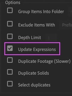
Update Expressions option.Multiple Grids Setup
With a little tweaking, this grid system can be expanded to as many grids as we want (or that AE can handle). We'll walk through a setup of 2 stacked grids, but the expressions used can be applied to grid systems of any size.
Note: We have included a Dropdown Menu control to select whether to stack the grids horizontally or vertically. This is found in the Multi Grid Controls layer in the Sliding Grid - Double comp. Then, each grid in that same comp has its own dropdown menu, allowing to choose whether the grid is positioned left or right (or top/bottom if the vertical stack option has been chosen).
First off make sure that the compositions are named differently, this is important since the expressions will reference those names, hence they need to be unique. We've named them:
Sliding Grid - 1: Left Grid (Top if stacked vertically).Sliding Grid - 2: Right Grid (Bottom if stacked vertically).
So, to control how much of the composition width (or height if stacked vertically) each grid will cover, we can use a slider control. We'll be using the slider value to define a percentage of the total comp width (or total comp height) - where at 50, both grids take up 50% (half) of the comp space. We've named this slider: Partition, and it's found in the Multi Grid Controls layer's effects panel.
Multi Grid Position Expression
Applied to each grid's position property within the Sliding Grid - Double comp.
const grid = comp(name);
const partition = thisComp.layer('Multi Grid Controls').effect('Partition')('Slider').value/100;
const stack = thisComp.layer('Multi Grid Controls').effect('Stack')('Menu').value;
const align = effect('Grid Position')('Menu').value;

// HORIZONTAL STACK
const x_horz =
	  align == 1 ?
	  grid.width/2 * partition * scale[0]/100 :
	  thisComp.width - grid.width/2 * (1-partition) * scale[0]/100;
const y_horz = thisComp.height/2;

// VERTICAL STACK
const x_vert = thisComp.width/2;
const y_vert =
	  align == 1 ?
	  grid.height/2 * partition * scale[1]/100 :
	  thisComp.height - grid.height/2 * (1-partition) * scale[1]/100;

const x = stack == 1 ? x_horz : x_vert;
const y = stack == 1 ? y_horz : y_vert;

[x, y]
Multi Grid Width Expression
Applied to the Grid Width slider in each Grid Precomp's Grid Controls layer.
const main_comp = comp('Sliding Grid - Double');
const partition = main_comp.layer('Multi Grid Controls').effect('Partition')('Slider').value;
const stack = main_comp.layer('Multi Grid Controls').effect('Stack')('Menu').value;
const align = main_comp.layer(thisComp.name).effect('Grid Position')('Menu').value;

const w =
	  align == 1 ?
	  thisComp.width * partition/100 :
	  thisComp.width - thisComp.width * partition/100;

stack == 1 ? w : value;
Multi Grid Height Expression
Applied to the Grid Height slider in each Grid Precomp's Grid Controls layer.
const main_comp = comp('Sliding Grid - Double');
const partition = main_comp.layer('Multi Grid Controls').effect('Partition')('Slider').value;
const stack = main_comp.layer('Multi Grid Controls').effect('Stack')('Menu').value;
const align = main_comp.layer(thisComp.name).effect('Grid Position')('Menu').value;

const h =
	  align == 1 ?
	  thisComp.height * partition/100 :
	  thisComp.height - thisComp.height * partition/100;

stack == 2 ? h : value;
Understanding the Math
Let's dive into the math for the two grids stacked horizontally:
Note: the same theory applies to the vertical stack except instead of the width and x position we'd be dealing with the height and y position.
We start off by referencing the grid precomp with it's name (remember to assign unique names to each grid comp for this purpose) - we'll reference its width later on.
Next, we reference the Partition slider. Since we are using a percentage scale for its value, we need to divide this by 100 to obtain a fraction (e.g: 25% = 25/100 = .25).
Note: When working with percentages we can consider these as portions of a whole, where that whole can be 1 - so a portion will always be less than 1, known as a fraction. We can express this portion as a percentage by multiplying it by 100, or just keep it as a fraction instead.
Since we are working with two horizontally stacked grids, the Partition value directly affects the x position of each grid.
To solve the position, we first have to multiply each grid precomp width by the Partition value to find how much space of the main comp it occupies (we are essentially translating this occupied space from a percentage to a pixel value). For the left grid we can use the base Partition value as a fraction (e.g. if set at 25% we can multiply the left grid width by .25), but the right grid needs to be multiplied by the remaining value - in our example .75. So for the right grid calculation we'll subtract the Partition's fractional value from 1 (a whole).
Here's a quick practical example, with our main comp and both grid precomps at 1920x1080 pixels in dimensions.
The Partition slider value is set to 25%, indicating that the left grid covers 25% of the space and the right grid the remaining 75% .
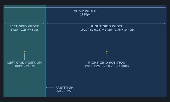
25%In pixels, the left grid therefore resizes to 1920 * 0.25 = 480px.
Whereas the right grid resizes to: 1920 * (1-0.25) = 1920 * 0.75 = 1440px.
Now we have to translate those width values to position values.
First we have to consider that the anchor point is at the center of each precomp. The x position of a layer is relative to it's anchor point so, back to our example: if the left grid width is 1920px, the x position would be 1920/2 = 960px, therefore if the new width (set by the Partition at 25%) is 480px, the new x position would be 480/2 = 240px.
Now for the right grid, since it covers the remainder of the main comp space, we can calculate the new x position by subtracting the new width (divided by 2) from the end of the comp instead: 1920 - (1920/2 * 0.75) = 1200px.
Conclusion
We hope you'll find this rig useful for your projects but, most importantly, that you've grasped the logic behind it - allowing you to customize the rig or build new similar templates from scratch.
To make it even more versatile, consider setting it up as a Motion Graphics Templates to use in Premiere Pro.
Additional Resources